
China Copper-Nickel-Chrome Barrel Plating Equipment for High-Performance Finishing
2026-08-23
Ever wondered why some copper-nickel-chrome barrel plating lines consistently hit spec while others struggle with uneven deposits and costly rework? The answer often lies in the equipment itself. Enter Junda, a Chinese manufacturer that has quietly become a benchmark for high-performance finishing machinery. In this post, we’ll take a closer look at what sets their barrel plating systems apart—and why it matters for your bottom line.
How Perforation Size and Barrel Open Area Affect Deposit Uniformity
In barrel plating, perforation size acts as a throttle for solution exchange. Small holes keep tiny parts from escaping but can starve the interior of fresh electrolyte, leading to thicker deposits near the barrel walls and thin, patchy coverage in the center. Large perforations improve flow but may let delicate components slip through or jam, so the hole diameter is usually matched to the smallest part dimension rather than chosen for conductivity alone.
The open area ratio, which reflects how much of the barrel surface is actually cut away, determines how evenly current reaches the workload. A low ratio restricts ion movement and forces current to concentrate at the outer edges, creating the classic dogbone effect on flat parts. Raising the open area helps flatten the deposit thickness but also weakens the barrel structure, so designers often reinforce the shell with ribs or use staggered hole patterns instead of simply drilling more holes.
Finding the right combination involves testing across mixed part geometries. A barrel with moderate perforation size and an open area around 15 to 20 percent often works for general-purpose plating, but very fine or oddly shaped parts may require smaller holes and higher rotation speeds to avoid shadowing. Tracking thickness variation across a sample batch gives a clearer signal than any single rule of thumb.
Balancing Current Density Across Mixed Parts in Copper-Nickel-Chrome Cycles
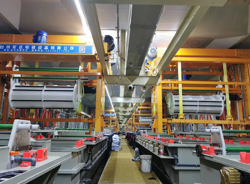
Plating racks that hold a mix of part sizes rarely see uniform metal distribution without deliberate intervention. A small bracket next to a large housing draws current at a much higher density, so the chrome layer builds faster on the bracket while the housing stays thin in recessed areas. Operators often notice this as dull or burnt deposits on edges and bright but insufficient coverage near the center of larger pieces. The problem compounds across the copper-nickel-chrome sequence because each layer inherits the thickness pattern of the previous one, magnifying surface roughness and dimensional drift.
Practical balancing starts with rack layout rather than rectifier settings alone. Spacing smaller parts farther from the anode or grouping them near non-conductive shields reduces their current draw, while large flat surfaces benefit from auxiliary anodes or conforming shields that redirect current into low-density zones. Some shops use bipolar dummy parts mounted adjacent to high-current areas to absorb excess current, effectively acting as sacrificial thieves. Adjusting anode-to-cathode distances per rack zone, rather than treating the whole load as one electrical unit, gives a finer balance without changing the bath chemistry.
Once a baseline is set, verifying the distribution under actual production conditions matters more than relying on a single test panel. Hull cell checks can predict the plating range, but mixed parts introduce edge effects and shadowing that lab tests miss. Periodic thickness mapping on a few sacrificial pieces from different rack positions shows whether the balance drifts as anodes dissolve or contacts wear. Small tweaks—raising a shield by a few millimeters, repositioning a thief, or slowing the entry speed into the chrome tank—often bring the spread back into tolerance without overhauling the entire line.
Drag-Out Reduction as a Daily Cost and Quality Lever
Every liter of process solution that clings to parts as they leave a tank is chemistry that never does its intended work. In electroplating, anodizing, or conversion coating lines, this quiet loss drains budgets through higher chemical top-ups, increased waste treatment loads, and more frequent bath analysis. The fix starts with simple operational discipline: slow withdrawal speeds, allow extra drain time over the tank, and position parts so solution runs back instead of pooling in recesses. Even a two-second longer dwell can cut chemical consumption by ten to twenty percent on busy lines, with zero capital outlay.
Beyond cost, drag-out is a direct quality lever. Carried-over solution contaminates rinse baths and downstream processes, leading to roughness, staining, adhesion failures, and unpredictable bath life. When less solution travels forward, rinses stay cleaner longer, the next tank's chemistry remains stable, and the line runs with fewer rejects and rework loops. Simple retrofits like drip trays, air knives, or low-pressure blow-off stations above high-value baths typically pay for themselves within weeks—not months—by slashing both chemical waste and defect rates.
To make drag-out reduction stick, treat it as a measurable daily habit rather than a one-time project. Track chemical addition volumes and rinse conductivity trends; a gradual upward slope often signals growing carryover. Use visual cues such as colored drip pans under racks to flag excessive drag-out at a glance. During shift walks, supervisors can spot hotspots—dense racking, awkward part orientation, or operators rushing transfer—and correct them on the spot. Over weeks, these small daily adjustments compound into a significant cost advantage and a noticeably more stable surface finish.
Preventing Part Nesting with the Right Barrel Speed and Fill Ratio
Part nesting is a frequent headache in injection molding when small or thin-walled components cling together after ejection, often because the melt hasn't been conditioned consistently. Barrel speed and fill ratio play a direct role here: if the screw turns too fast for a given shot size, you get uneven shear heating and variable melt density, which can leave parts softer or stickier than intended.
To prevent this, match barrel speed to the material's thermal sensitivity and the mold's fill requirements. A slower screw rotation with a well-chosen fill ratio—typically 60-80% of shot capacity—ensures the resin melts uniformly without overheating or degrading. Lower fill ratios give the screw more time to convey and plasticate, reducing localized hot spots that cause parts to fuse or nest after cooling.
On the production floor, start by reducing barrel speed 10-15% while keeping the fill ratio in the mid-range. Watch for signs like short shots or surface splay, which indicate under-plasticization, then fine-tune upward. The goal is a melt that releases cleanly from the mold every cycle, so parts separate on their own instead of sticking together.
Electrolyte Filtration and Agitation Tuning for Dense Chrome Top Coats
Building a dense chrome top coat isn't just about the chemistry in the tank—it's about how clean and how active that chemistry stays during deposition. Filtration removes suspended solids and colloidal debris that would otherwise embed in the growing chromium layer, creating pinholes or soft spots. A filter setup that's too coarse lets fine particulates slip through, while one that's too fine can disrupt flow patterns near the cathode. Getting the pore size and flow rate right means more uniform nucleation and fewer microscopic voids.
Agitation plays an equally subtle role. Without enough movement, the diffusion layer near the part thickens, starving the surface of fresh chromium ions and leading to dull or burned edges. But aggressive stirring can strip away the very polarization conditions that encourage a dense, crack-free deposit. Many platers find that a gentle, laminar flow across the part—rather than turbulent mixing—promotes the tight grain structure typical of hard chrome top coats. Pulsing the agitation or adjusting impeller placement can make the difference between a mediocre build and a truly dense finish.
Practical tuning often means running a few test panels while varying both filter micron rating and agitation speed in small steps. You'll typically see a sweet spot where brightness peaks and micro-crack networks become more uniform. Documenting those settings pays off, because the same electrolyte can behave differently after a few hours of use as organic byproducts accumulate and conductivity shifts. Slight adjustments to filtration pressure or agitation cadence can then restore the original deposit density without changing the bath formulation.
Running a 24-Hour Acceptance Trial Without Slowing Down Your Line
The trick is to treat the trial as an overlay rather than a separate event. Instead of stopping the line for a dedicated acceptance window, we piggyback on existing production runs, pulling samples at predetermined intervals and checking them against a lightweight pass/fail list. This way the line keeps its rhythm, and the acceptance data comes from real operating conditions rather than an artificial staged demo.
One thing that often gets overlooked is shift handoff. If the trial is going to run for a full day, you need to brief both shifts on what to watch and what to record. Keep the observation sheets simple—no more than a handful of parameters—so operators don't feel like they're babysitting a science project. A quick huddle at changeover, with a designated point person per shift, prevents gaps in the log and keeps everyone comfortable that the trial isn't adding extra workload.
Finally, plan for a controlled rollback. Even with careful overlay testing, there's a chance a failed checkpoint will force you to isolate the new equipment or process. Have bypass valves, backup tooling, or a manual fallback ready to go in minutes. The goal isn't to prove it works at all costs; it's to see how it behaves under normal line pressure, then make the go/no-go call without drama.
FAQ
Small to medium-sized components that can tumble without damage—fasteners, stampings, connectors, decorative hardware. Parts need enough weight and shape to circulate freely inside the barrel, and blind holes or deep recesses usually require auxiliary anodes or special barrel designs.
Copper fills minor surface defects and promotes adhesion, nickel builds thickness and acts as the main barrier layer, and chrome adds hardness plus tarnish resistance. Together they handle moisture, mild chemicals, and everyday wear far better than a single metal layer.
Look for variable speed drives that maintain smooth rotation without slipping, current-carrying danglers or center bars rated for the full load, and rectifiers with ripple below 5% for nickel and chrome. Overheating signs, weak contacts, and thin bus bars often cause uneven deposits.
Many Chinese manufacturers now use imported rectifiers, PLC controls, and PP or PVDF barrel materials. The key is not the country of origin but the factory's engineering capability, weld quality, and willingness to share detailed drawings and previous installation references.
Yes, but the bath chemistry and operating parameters differ. Decorative chrome usually follows bright nickel with a thin chromium layer, while functional or hard chrome requires higher current densities, longer plating times, and often a different barrel rotation speed to avoid burning.
Daily checks on electrical contacts, anode cleanliness, and barrel perforation; weekly bath analysis for copper, nickel, and chrome concentrations; monthly cleaning of filters and heat exchangers. Neglecting anode bags or letting sludge build up changes current distribution quickly.
Automotive interior and underhood fittings, sanitary ware, electrical connectors, furniture hardware, and consumer electronics. Any sector needing high-volume small parts with a bright, wear-resistant finish is a likely fit.
Conclusion
Getting a uniform deposit across every part in a barrel starts long before the rectifier is switched on. On China-built copper-nickel-chrome lines, the relationship between perforation size and total open area in the barrel wall dictates how quickly fresh electrolyte reaches recessed surfaces and how spent solution drains away. Too little open area traps metal-poor liquid in the load; too much weakens the barrel and lets small parts wedge into holes. In mixed-part cycles, balancing current density means grouping parts by surface area rather than by part number alone, so a small fastener does not steal current from a larger bracket. Drag-out reduction is equally practical: a slower withdrawal speed, a short drip zone over the process tank, and correctly sized drain holes can cut chemical loss and reduce rinse contamination without adding capital cost.
Preventing part nesting is less about luck and more about matching barrel speed and fill ratio to the geometry of the load. A fill ratio above about one-third often causes parts to lock together, especially when flat or cup-shaped pieces are mixed with heavier solids; a slightly lower fill and a gentler rotation keep the load tumbling instead of sliding as one mass. For dense chrome top coats, filtration and agitation tuning matter as much as the chrome bath chemistry. Fine filtration removes suspended solids that would otherwise create rough, dull patches, while controlled air or mechanical agitation prevents temperature and concentration stratification near the anode. Finally, a 24-hour acceptance trial does not have to slow the line if it is run as a side-by-side batch on the same rectifier schedule, with sampling at each plating stage rather than a full shutdown. This gives realistic deposit thickness and appearance data without disrupting daily output.
Contact Us
Contact Person: hayyr
Email: [email protected]
Tel/WhatsApp: 8613082110525
Website: https://www.jundaelectroplating.com