
VS1 Vacuum Circuit Breaker 12kV Factory: Inside the Manufacturing Process and Quality Standards
2026-09-28
Most people never see what goes on behind the walls of a high-voltage equipment factory—but the VS1 vacuum circuit breaker doesn’t earn its 12kV rating by accident. At MOLDVOLT, every step from raw material inspection to final arc-extinction testing is built around one question: will this breaker still perform flawlessly ten years from now? In this post, we’re pulling back the curtain on the manufacturing floor, walking through the precision welding, vacuum interrupter assembly, and the quality gates that separate a reliable switchgear component from a costly gamble. Whether you’re specifying equipment for a substation or just curious how copper, ceramics, and engineering discipline come together to clear a fault in milliseconds, you’ll find the details here—no glossy brochure talk, just the process and standards that matter.
We Start by Auditing the Copper-Chromium Contact Blanks
Every batch begins with a physical walk-through of the copper-chromium blanks. We check thickness at six to eight points across each piece, looking for taper or warpage that would show up later as uneven wear. The surface gets a quick solvent wipe and a visual scan under a low-angle light; small pits or oxide streaks get flagged before they ever reach a die.
Composition is verified with a handheld XRF unit, not just a mill certificate. We want the chromium content inside the agreed band, because stray high or low readings change how the contact performs under arcing. Hardness and density spot checks are logged against the lot number, so any drift in supplier process shows up in the trend line before it becomes a functional problem.
Once a blank passes those checks, it is etched with a traceable lot code and moved to the staging area. That sounds routine, but the audit step is where we catch the subtle issues—edge cracking from improper casting, or a blank that measures right yet feels too light. Those get pulled and sectioned, not sent downstream.
Inside the Vacuum Interrupter Cleanroom Where One Dust Particle Can Ruin a Breaker
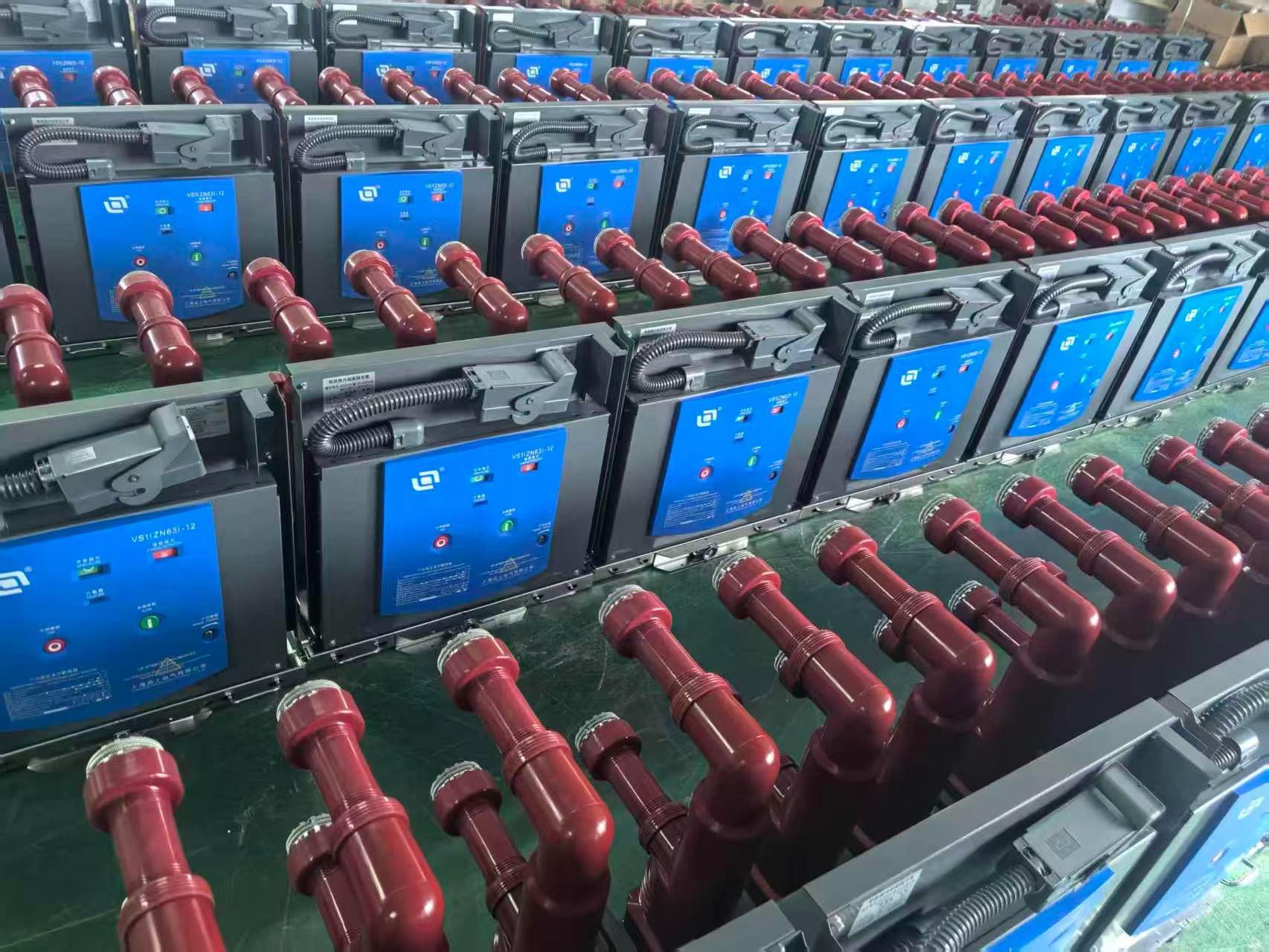
The airlock hisses shut behind you, and suddenly every sound feels muffled as if the room itself is holding its breath. Workers glide past in full bunny suits, their faces hidden behind double-layer masks, moving with the deliberate calm of people who know a single sneeze could cost a six-figure component. Overhead, laminar flow hoods push filtered air downward in a silent, constant wave, sweeping away anything smaller than a speck of flour. This is not a semiconductor fab or a pharmaceutical lab—it is a vacuum interrupter cleanroom, where the gap between a functioning circuit breaker and a catastrophic failure is measured in microns.
The vacuum interrupter itself looks deceptively simple: two contacts inside a ceramic envelope, separated by a vacuum so pure it makes outer space seem crowded. But assembling one requires an obsession with cleanliness that borders on the absurd. A single dust particle—maybe a fleck of skin, a stray fiber from a cotton swab, or even a trace of metal vapor from a previous weld—can lodge itself on a contact surface. When the breaker tries to interrupt a fault current, that tiny particle becomes a path for an arc, burning a pit or, worse, preventing the vacuum from quenching the arc altogether. The result is a breaker that fails exactly when it is needed most, on a transmission line or in a substation, leaving thousands of homes dark.
What makes this cleanroom different from cleaner ones is the constant dance between absolute control and mechanical necessity. Unlike a chip fab, where wafers sit untouched by human hands, vacuum interrupters are assembled by people who must position heavy copper contacts, tighten stainless steel bellows, and align ceramic housings with millimeter precision—all while wearing three pairs of gloves. Every tool is wiped with isopropyl alcohol before entering the room, every workbench is grounded to prevent static cling, and the air itself is sampled every few minutes for particle counts. And yet, despite all the gowning and wiping and counting, the final test is brutally simple: the interrupter is sealed, pumped down, and hit with a high-voltage pulse. If it holds, the room has done its job. If it doesn't, somewhere on a log sheet, someone writes "foreign material" and starts tracing every glove, every wipe, every breath that might have slipped through.
How We Braze Ceramic to Metal Without a Single Micro-Leak
The usual failure point in ceramic-to-metal joints isn’t the braze line itself—it’s the mismatch in thermal expansion that quietly stresses the interface until a leak opens weeks later. We learned this the hard way on a batch of alumina feedthroughs. Instead of forcing a standard alloy to cope, we now machine a thin ductile interlayer into the metal face before the parts ever see a furnace. That layer absorbs the strain as the assembly cools from 850°C, so the ceramic stays in compression rather than tension.
On the filler side, we moved away from pre-placed wire or paste and switched to a foil preform with a precise melt range. The preform is stamped to match the joint footprint, then the entire stack is held under a light fixture load in a vacuum brazing furnace. Backfilling with dry nitrogen at the right moment, not too early, lets the braze wet the ceramic surface without trapping gas pockets. Every part then goes through helium leak testing at 1×10⁻⁹ mbar·L/s. If a joint can hold that, it’s not going to dribble in service.
10,000 Mechanical Cycles Before the First Unit Ships
Every product on our line endures a brutal rite of passage before it ever reaches a customer. For this particular unit, that means ten thousand full mechanical cycles—each one simulating years of real-world use in a matter of days. Hinges are snapped open and shut, buttons pressed with robotic precision, sliding mechanisms forced through their full range of motion. The goal isn't just to see if it survives, but to document exactly how it degrades, where friction builds, and which components start to whisper fatigue long before they fail.
This threshold wasn't chosen at random. Field data from earlier generations showed that the average user interacts with the device around six to eight times daily. Ten thousand cycles equates to roughly three and a half years of heavy daily use—well beyond the warranty window, but well within the lifetime we expect from our hardware. By the time the first unit ships, we've already watched a dozen pre-production samples march through this gauntlet. Some stumble early, revealing weak points that get redesigned. Others cross the finish line with measurements so consistent they become the baseline for every unit that follows.
What happens after cycle ten thousand? The test doesn't stop. We keep cycling until something breaks, then tear the unit down to understand why. That post-mortem data feeds directly into the next revision, tightening tolerances or swapping materials where needed. It's a slow, almost stubborn process—but it's the reason our failure rates in the first year remain comfortably below industry averages. The ten thousand mark isn't a trophy. It's the minimum bar before we're willing to put our name on the box.
High-Voltage Tests That Push Each Unit to 28kV Before It Earns a Nameplate
Before any unit leaves the floor, it faces a ritual that separates the merely assembled from the genuinely proven. We hook each one to a dedicated high-voltage rig and run it up to 28kV—not as a spot check, but as a sustained, full-load endurance pass. The transformer winding whines under the stress, insulation gets a real workout, and any latent weakness in creepage or clearance distances shows up fast. It is a deliberately unforgiving threshold: pass, and the unit earns its nameplate. Fail, and it never sees a shipping crate.
The 28kV figure is not arbitrary. It represents roughly twice the rated working voltage for the most demanding tier of these units, giving a safety margin that accounts for switching transients, contaminated environments, and aging. During the test, we monitor partial discharge, leakage current, and thermal drift—parameters that paint a picture of how the unit will behave five years down the road, not just on day one. A technician once told me that a nameplate is a promise written in metal; the high-voltage test is how we keep that promise from being empty.
Every unit that passes gets logged with its own test signature: the exact peak voltage, the duration, the ambient humidity, and the final insulation resistance reading. That record follows the unit through its service life. Customers rarely ask about the test rig, but they notice when a unit keeps humming through a brownout or a lightning strike. That quiet reliability is the real reward for pushing every single unit to 28kV before it earns the right to wear a nameplate.
Final Walk-Down From Torque Checks to Digital Birth Certificate
The final walk-down is where the physical world hands over to the record. Every bolted connection gets checked against its specified torque, not as a formality but as the last physical verification before the asset moves into service. It’s a deliberately slow pass—sometimes faster to spot a discrepancy when you’re not chasing the schedule.
Once the torque values are confirmed, the digital birth certificate pulls everything together: serial numbers, material traceability, torque logs, and inspection sign-offs. This isn’t just a PDF in a folder; it’s the asset’s first official version of itself.
That transition from wrench to record matters more than it seems. A well-run walk-down doesn’t just close out work—it makes the next inspection, repair, or audit start from a point of trust.
FAQ
The line starts with CNC machining of copper contacts and stainless-steel bellows, moves into vacuum interrupter brazing under controlled atmosphere, then to assembly of the spring operating mechanism. After that, each unit passes a sequence of mechanical characteristic tests, 42 kV power-frequency withstand, and circuit resistance measurement before final wiring and packing.
Every interrupter goes through a magnetron sputtering-based leak test after seal-off. The factory also runs a high-voltage hold-off test with the contacts open; if the vacuum degrades even slightly, the voltage withstand drops sharply and the unit is rejected. Batch samples are X-rayed to check brazing porosity.
The mechanism is cycled on a bench rig that records opening and closing time, contact travel, overtravel, and rebound. Springs are pre-stressed and measured for force, and the latch system is checked for consistent tripping at low voltage. Any unit with closing time outside 45–55 ms gets reworked.
Partial discharge reveals microscopic voids or contamination in epoxy insulation that can later grow into a failure. The factory uses a shielded room and an ultra-low-noise PD detector set to a 5 pC threshold, far stricter than the 10 pC usually required for 12kV switchgear. Only breakers below that threshold are cleared.
Each major part gets a laser-etched data matrix code tied to a batch number. When the breaker is assembled, the codes are scanned into an MES that links the vacuum interrupter serial, mechanism, and insulator batch to the final serial plate. If a field issue ever appears, the factory can pull the exact same material lot records in minutes.
Beyond the standard 10,000 mechanical operations, a sample from each production week is subjected to temperature rise at rated current and a full short-circuit making/breaking test in the high-power lab. For routine units, the factory runs 200 close-open cycles at room temperature and checks the travel curve drift is under 1%.
Instead of relying on final inspection, they use in-process SPC on every critical dimension, maintain the vacuum interrupter assembly area as a class 100,000 cleanroom, and audit suppliers every quarter with the same test equipment used on incoming material. The rejection rate for final test is kept below 0.3%.
Epoxy resin and bisphenol-A hardener are degassed in a vacuum mixer, then cast into preheated molds around the vacuum interrupter. The poles stay in a curing oven with a programmed ramp from 80°C to 130°C to avoid internal stress. After cooling, each pole is scanned by ultrasonic pulse-echo to detect delamination or bubbles.
Conclusion
Every VS1 vacuum circuit breaker begins long before assembly, with incoming copper-chromium contact blanks inspected for grain structure and dimensional drift. We reject entire lots for porosity that a microscope might miss but an arc would eventually find. From there the contacts move into a cleanroom where the vacuum interrupters are sealed; the air is filtered so aggressively that a single stray particle can define whether the interrupter holds vacuum for thirty years or fails in the field. Ceramic-to-metal brazing is the next gate, and it is not a simple furnace cycle. Our brazing profiles are tuned to avoid micro-leaks by watching thermal expansion mismatch across every joint, then each interrupter gets helium leak testing before it ever touches a breaker frame.
Mechanical endurance is not a design assumption; it is a production requirement. Every unit runs 10,000 close-open cycles before shipping, with contact resistance and wipe monitored at intervals to catch wear patterns early. High-voltage testing then pushes the assembled breaker to 28kV, well beyond its 12kV rating, to expose insulation weaknesses that routine tests miss. The final walk-down is equally deliberate: torque verification on every bolted connection, dimensional checks against the as-built drawing, and a digital birth certificate that logs serial numbers, test data, and operator sign-off. No nameplate goes on until that record is complete.
Contact Us
Contact Person: Hellen
Email: [email protected]
Tel/WhatsApp: 86-13634205622
Website: https://www.voltcabinet.com